This was a project from last Halloween, but I'm just now getting to posting the build log to my page. Bits and pieces have been previously posted on Halloween Forum/YouTube/Facebook.
One of my buddies with a 3d printer offered to make me some parts so I was inspired to make a haunted pumpkin patch out of Dollar tree pumpkins hacked to move with servos.
I designed this hinge to work with a MG90S servo. It’s a common microservo.
With a little hot glue, the curved hinge fits perfectly within a bisected DollarTree pumpklin
So I spent some time working on my pumpkins. I used a hot knife to cut each one in half with mouth and eyes. Then I used a hot glue gun to mount the servo hinge mechanism and a flicker LED.
I painted the insides black and sculpted some loctite foam into better stems. Then I glued some PVC to the bottom so I can stablilize them in the ground.
Finally I repainted the outsides orange and added a little wash to make the stems pop.
Here’s the final assembled board for the project. Controls six servos with random movements and synchronizes movements with on the board audio player triggered by a PIR sensor. Coded by Arduino IDE.
Here's the final installed project. All of the pumpkins randomly open and close, but when someone walks by and triggers the PIR sensor, they all start laughing.
I’ve been working on a new board at Jekyll-Labs. The Howler board provides a customizable sound effect that is triggered by motion. It’s a very simple board that allows the JQ8900 audio board and the SR602 PIR sensor to talk to each other. Additionally, it provides easily accessible connections for audio out and multiple options for providing power.
Use cases for the Howler board:
Jump Scares— Have a prop that you want to growl or laugh when someone walks by? The Howler board is perfect for this.
Haunt Introductions—The Howler board can read off instructions whenever a guest walks into the haunt.
Ambient music—You have some background noise/music you want to play when people are in the haunt, but not all the time.
Audio output:
The JQ8900 includes a 3W amplifier so it works with unpowered speakers. 3W is great for props. You’re not going to deafen anyone, but it’s plenty loud enough for a surprise. I like “marine” speakers from Amazon, but Goodwill also may have options. The Howler board lets you connect your speaker via a standard 2 pin header interface. The board also includes a 3.5mm “headphone” jack for line level output. Plug in a set of computer speakers or even a subwoofer for some bone rattling base.
Computer Interface:
The JQ8900 has a female micro-usb port. If you plug it into your PC via a cable, your computer will recognize it as a thumb drive. Then just drag and drop your MP3 audio file. As long as it’s named 00001.MP3 , the board will play it when triggered. (Do disconnect the board from any power before plugging into your computer).
Power supply:
The Howler board includes a voltage regulator it so can operate on HI (nominally 12v, but potentially 7-18v) or LOW (nominally 5v, but good potentially down to 3.3v) power supply options. This makes it easy to integrate either into a 12v DC haunt set up or work with batteries in a more remote set-up. Importantly, only one set of the Howler board power connections should be attached at a time. Having them both connected could cause damage to the voltage regulator.
My talking skeleton (Jawduino method) has been hooked up to a Raspberry Pi for a few years. This year, I have the Pi accessing a voice agent from Character.AI. The audio output from the Pi triggers the jawduino and allows a reasonable AI conversation.
Character.AI voice agents have great latency with minimal delay. This video uses an agent named “funny bones” who was trained on more creative material and is able to tell some good Halloween stories. A word of caution, however: the voice agents from character.AI are utterly pathologic liars. If something is not immediately in their training, they will just make up a response on the spot. The agents will go into standby mode if you don’t talk to them, but can be brought back with a click or two. Here’s a link to Funny Bones, if you’d like to try it out yourself.
I’ve also experimented with voice agents from Supernormal. Supernormal AI voice agents are more built for telemarketing, but I gave this particular voice agent “HauntedSkull” a set of instructions that makes him ready for trick or treaters. Supernormal AI voice agents are much more trustworthy (and I think tell better jokes), but a conversation can only last 10 minutes, and is a bit cumbersome to restart. Here’s a link to HauntedSkull if you’d like to try him out—
I’ve written previously (here) about the Flicker LED Amplifier Circuit. Basically, the circuit uses the flickering pattern of a small cheap LED to drive that same flickering pattern in a much brighter LED. If you’d like to build your own, the schematic is posted in my original blog post (linked above). This new board allows you to assemble the circuit in a much more compact form factor. To assemble, you need, the mini-flicker LED board, a flicker LED, two 470 ohm resistors, a N-channel Logic MOSFET (I recommend the FQP30N06), and a couple wires.
This is a great starter soldering project, and an experienced hand should be able to fully assemble the board in less than 5 minutes. I even put together a video showing the process.
It can easily handle the current for several larger automotive LEDs when they are wired in parallel. For spot lights I like the Eagle Eye LED’s. Perfect for lighting a scene or tombstone. They come in great colors and project a lot of light. They are advertised as 9W, but actually draw about 0.7W at 12vDC.
For a more diffuse lighting solution, I like the LED dome light replacements. They come in a variety of different brands, but essentially are five 5050 LED’s mounted on a 194/T10 bulb base. These cast light in all directions and use 0.6W at 12vDC. Perfect for inside a pumpkin.
I still really like the WAGO 221 connectors. They make solid connections to a wide range of different gauge wire. They are fully reusable. And come in a variety of different sizes. I did the film canister thing (see this post) for a few years, but water sometimes still got in, and it was a pain to cut the film canister lids.
Last year I decided to take my electrical enclosures in a different direction. Rather than maximizing waterproofing, I decided to maximize water drainage. I’m now mounting my boards and connectors about a foot off the ground and covering with a black painted deli container.
This design was really made possible by some 3D printed WAGO-221 brackets. I found these plans on Thingiverse. I had a few printed and they are great.
***First, a caveat—do not give these to kids. Button batteries seem harmless, but they’re actually really dangerous. When swallowed, they lodge in the esophagus and cause horrible corrosion and perforation. Bad stuff. Trust me on this one. ***
Most folks may have heard of LED Throwies—a disc battery, one LED, some tape and a magnet create a glowing light that can be tossed onto a high metal sign or post and will glow for days to weeks. I decided to make a 3D printed skull version of one. You don’t need much: the 3D print, a 10mm LED, and a CR2032 battery. You might need some tape or hot glue, but often sticks in without either.
I’ve gotten a few questions about the PIR sensor enclosures I use. My sensor of choice is the SR602 it accepts a supply of 3.3-18 V and outputs HIGH (3.3V) for 2 seconds when movement is sensed. The form factor is the real reason I prefer it, though. The circuit board for the SR602 is circular and fits perfectly inside a 1/2” PVC fitting.
My enclosure is based in no small part on the work of Halstaff, the great one. Mine has fewer parts and a slightly different form factor, but he certainly inspired me. If you haven’t seen his videos, do yourself a favor and check out is work. He’s sadly no longer with us, but I like to think of him as still working with the haunt community (just perhaps from the other side).
Both Sparkfun and Arduino.cc have great tutorials on this subject (most of these pictures below are taken from these sites). Links are at the bottom.
If you can program an Arduino, you can program a Twitch-n-Howl board. That's because both boards use the same ATmega328 chip to store and execute code. In order to save space, the Twitch-n-Howl board does not have a USB port. In order to upload code, you will need to set up a dedicated Arduino as a "Programmer" and connect that Arduino to the ISP header of the Twitch-n-Howl.
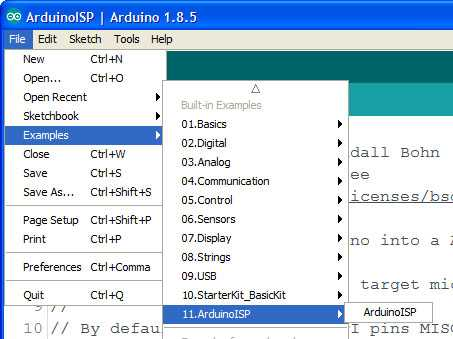
First connect your "Programmer" board to your computer and upload the ArduinoISP.ino file. This is located in the Examples in the File menu. Upload this just like any other sketch.
Now you can connect your programmer board (I'm using a Sparkfun Redboard Arduino Uno clone here) to the Twitch-n-Howl. I like using a clip with pogo pins (like this one), but you could also solder a pin header to the board and just use jumpers.
The pins have to be connected in a very specialized pattern
Uno Pin — Name — ISP Pin — Name — Uno Pin
12 MISO O O 5V 5V
13 SCK O O MOSI 11
10 Reset O O GND GND
Here’s what it looks like when connected with jumpers.
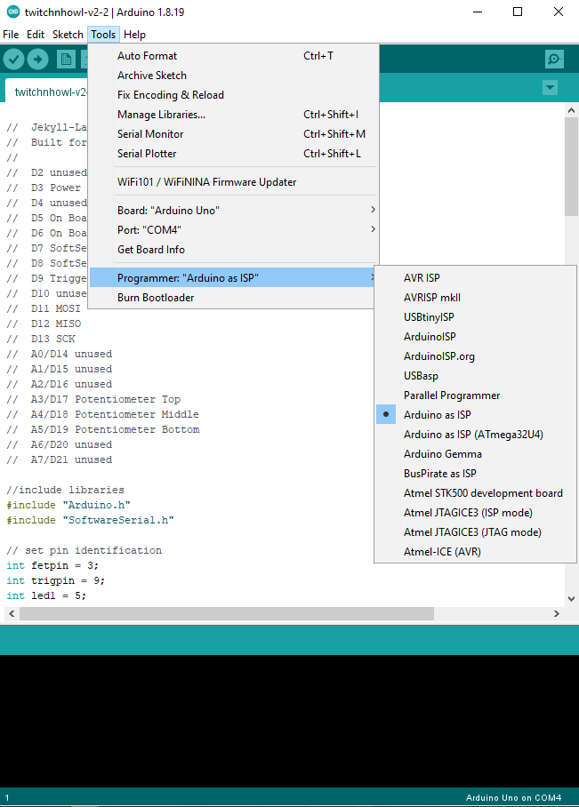
Then you simply put the code for the target board in the Arduino IDE (just like coding a board as usual). You will need to select “Arduino as ISP” as the programmer.
Then you can “Upload Using Programmer”. And, BOOM, your Arduino Uno Programmer board will add the brand new code to your Twitch-n-Howl board.
**On these links you'll see instructions for loading the bootloader onto a new ATmega328 chip. This will be unnecessary for the Twitch-n-Howl board as it has already been done at Jekyll-Labs. **
Removed (by adding //) the option for continuous on. I've burned out too many (2) door lock actuators by having the interval potentiometer go to zero. Now it will just fire same duration, but more frequently.
//  Jekyll-Labs Twitchy Attiny85
//  Built for Twitchboard v1.7
//

// Pin definitions
int fetpin = 0;
int trigpin = 3;
int potpin = A2;

// global variables
long duration = 200; // duration in miliseconds (200)
long PWM = 255; // Duty cycle 0-255 (255)
long intervallow = 1000; // low end of interval range in sec [2 sec]
long intervalmid = 10000; // middle of interval range in sec [10sec]
long intervalhigh = 90000; // high end of interval range in sec [90sec]
long intervalmax = 36000000; // interval in sec if pot maxed out [10hrs]

// initialize global variables
long timeunit = 0;
unsigned long last = 0;
unsigned long timeinterval = 0;
float exprob=0.50;

void setup() {
  randomSeed(A1);
  pinMode(fetpin, OUTPUT);
  digitalWrite(fetpin, LOW);
  pinMode(trigpin, INPUT);
  pinMode(potpin, INPUT);
}

void loop() {
  // uncomment if pot controls duration
  // duration of signal will last from 0.5 - 10 sec
  //int durationpot = analogRead(potpin);
  //long duration = map(durationpot,100,1023,500,10000);
  //if (duration <500 controls="" duration="150;" fet="" for="" if="" int="" middle="" of="" pot="" pwm="map(PWMpot,0,1000,0,255);" pwmpot="analogRead(potpin);" read="" signal="" uncomment="">255) PWM = 255;

  // uncomment if pot controls frequency
  // mean frequency of random signals is 1 events per time unit
  int freqpot = analogRead(potpin);
  timeunit = map(freqpot,512,1023,intervalmid,intervalhigh); // 2nd half dial range
  if (freqpot>1000) timeunit = intervalmax; // far right dial 1hr
  if (freqpot<512 1st="" adjust="" and="" bottom="" check="" continous="" debounce="" dial="" for="" freqpot="" half="" if="" is="" of="" on="" positive.="" range="" timeunit="" trigger="">0) {
    int trigger = digitalRead(trigpin);
    if (trigger == HIGH) {
      delay(100);
      int trigger = digitalRead(trigpin);
      if (trigger == HIGH) {
        delay (100);
        int trigger = digitalRead(trigpin);
        if (trigger == HIGH) {
          timeunit = (duration * 2);
        }
      }
    }
  }

  // Calcuate time interval between events. timeunit depends on:
  // Potentiometer value if trig = 0
  // Duration multiplier (shorter) if trig = 1
  unsigned long timeinterval = exprob * timeunit;

  // Check if time interval has passed
  if ((millis() - last) > timeinterval) {
    last = millis(); // updates timer to last event
    analogWrite(fetpin,PWM);
    long thisduration = (0.5*duration) +random(duration);
    delay(thisduration);
    digitalWrite(fetpin,LOW);
    // the following equation runs once per event and
    // generates a random float (exprob) that falls in an
    // exponential distribution. It will be used to
    // determine the interval time for the next event.
    // Events that occur at exponentially distributed
    // intervals form poisson processes.
    exprob =  (-2)*(log((100-random(100))/100.00));
  }
  else digitalWrite(fetpin,LOW);

  delay(20);
}
//  Jekyll-Labs Twitch and Sound
//  Built for Twitchnhowl v2.2
//
//  D2 unused
//  D3 Power MOSFET (PWM avail)
//  D4 unused
//  D5 On Board LED1
//  D6 On Board LED2
//  D7 SoftSerial Tx
//  D8 SoftSerial Rx
//  D9 Trigger Input
//  D10 unused
//  D11 MOSI
//  D12 MISO
//  D13 SCK
//  A0/D14 unused
//  A1/D15 unused
//  A2/D16 unused
//  A3/D17 Potentiometer Top
//  A4/D18 Potentiometer Middle
//  A5/D19 Potentiometer Bottom
//  A6/D20 unused
//  A7/D21 unused

//include libraries
#include "Arduino.h"
#include "SoftwareSerial.h"

// set pin identification
int fetpin = 3;
int trigpin = 9;
int led1 = 5;
int led2 = 6;
int potMpin = A4;
int potTpin = A3;
int potBpin = A5;

//set SoftSerial for JQ8900 and basic Hex commands
SoftwareSerial mySoftwareSerial(8, 7); // RX, TX
byte playnext[] = {0xAA, 0x06, 0x00, 0xB0 };

// set global constants
unsigned long durationlow = 200; // low end of duration range in msec [0.2sec]
unsigned long durationhigh = 15000; // high end of duration range in msec [15sec]
long intervallow = 2000; // low end of interval range in sec [2 sec]
long intervalmid = 10000; // middle of interval range in sec [10sec]
long intervalhigh = 90000; // high end of interval range in sec [90sec]
long intervalmax = 36000000; // interval in sec if pot maxed out [10hrs]
unsigned long mosfetdelay = 0; // extra delay to turn mosfet on after audio triggered [0]

// initialize global variables
long timeunit = 12; // mean untriggered time interval (sec)
unsigned long last = 0;

unsigned long timeinterval = 0;
float exprob=0.50;

void setup() {
  // setup mosfet pin as output
  pinMode(fetpin, OUTPUT);
  digitalWrite(fetpin, LOW);

  // set up potentiometers and trigger pin
  pinMode(trigpin, INPUT);
  pinMode(potTpin, INPUT);
  pinMode(potMpin, INPUT);
  pinMode(potBpin, INPUT);

  // Set up and turn off LED
  pinMode(led1, OUTPUT);
  digitalWrite(led1, LOW);
  pinMode(led2, OUTPUT);
  digitalWrite(led2, LOW);

  // begin softserial for JQ8900
  mySoftwareSerial.begin(9600);

  last = millis(); // updates timer to start
  randomSeed(A0);

}

void loop() {
  // duration of signal will last from 0.5 - 10 sec
  int durationpot = analogRead(potBpin);
  long duration = map(durationpot,100,1023,durationlow,durationhigh);
  if (duration <500) duration = 150;

  // read middle pot for PWM of fet signal
  int PWMpot = analogRead(potMpin);
  int PWM = map(PWMpot,0,1000,0,255);
  if (PWM>255) PWM = 255;

  // mean frequency of random signals is 1 events per timeunit
  int intervalpot = analogRead(potTpin);
  long timeunit = map(intervalpot,512,1023,intervalmid,intervalhigh); // 2nd half dial range 12-60 sec
  if (intervalpot>1000) timeunit = intervalmax; // far right dial 1hr
  if (intervalpot<512) timeunit = map(intervalpot,75,512,intervallow,intervalmid); // 1st half dial range 0-12 sec
  if (intervalpot<75) timeunit = 0; // bottom of dial continous on

  if (timeunit<=0){ // continuous on if left dial all counter clockwise
    analogWrite(fetpin,PWM);
    digitalWrite(led2,HIGH);
  }

  else {
    // Check for trigger (X3 for debounce) and adjust
    // timeunit if trigger is positive.
    if (timeunit>0) {
      int trigger = digitalRead(trigpin);
      if (trigger == HIGH) {
        delay(100);
        int trigger = digitalRead(trigpin);
        if (trigger == HIGH) {
          delay (100);
          int trigger = digitalRead(trigpin);
          if (trigger == HIGH) {
            timeunit = 2000; // minimum mean interval in sec for triggered events
            digitalWrite(led1,HIGH);
          }
        }
      }
      if (trigger == LOW) digitalWrite(led1,LOW);
    }

    // Calcuate time interval between events. timeunit depends on:
    // Potentiometer value if trig = 0 (not triggered)
    // Duration multiplier (shorter) if trig = 1
    unsigned long timeinterval = exprob * timeunit;

    // Check if time interval has passed and if so trigger event
    if ((millis() - last) > timeinterval) {
      last = millis(); // updates timer to last event
      digitalWrite(led2,HIGH); // indicator LED
      mySoftwareSerial.write(playnext, sizeof(playnext)); // play next MP3
      delay(10);
      if (random(2)<1) mySoftwareSerial.write(playnext, sizeof(playnext)); // 50% of the time skip to next MP3
      delay(100 + mosfetdelay);
      analogWrite(fetpin,PWM);  // turn on mosfet
      delay(duration);
      digitalWrite(fetpin,LOW);
      digitalWrite(led2,LOW);

      // the following equation runs once per event and
      // generates a random float (exprob) that falls in an
      // exponential distribution. It will be used to
      // determine the interval time for the next event.
      // Events that occur at exponentially distributed
      // intervals form poisson processes.
      exprob =  (-2)*(log((100-random(100))/100.00));
    }
    else {
      digitalWrite(fetpin,LOW);
      digitalWrite(led2,LOW);
    }
  }
  delay(20);
}
Most
microprocessors generate pseudorandom numbers that follow a uniform
distribution. This is great for simulating things like rolling dice
where the probability of rolling a 1 is the same as rolling a 4. It
turns out, however, that for most natural processes, the time between
events is more accurately modeled using an exponential distribution of
random numbers. This results in both more clustering of events and
larger gaps in between them. These are called poisson processes because
the distribution of events-per-time-interval follow a Poisson
distribution.
In
both of the two samples below, there are twenty events per time
interval. In the first sample, events are spaced using a uniform
distribution of random numbers. In the second sample, events are spaced
using an approximate exponential distribution (thereby generating a
Poisson process).
It’s
a subtle difference, but the exponentially spaced events seem less
regular—they occur both earlier and later than expected. The Poisson
distribution has been fitted to a wide variety of natural events. Events
as varied as radioactive decay/clicks on a Geiger counter, lightning
strikes, and Prussian soldiers killed by kicking horses have all been
described as Poisson processes.
This default code for the Twitch-n-Howl board uses a mathematical transformation to convert the uniformly distributed pseudorandom numbers into exponentially distributed numbers.
where u is the uniformly distributed random number and lambda is the rate parameter (# of events per unit time)
This same transformation is depicted graphically below. The blue line shows a uniform distribution of random numbers, while the red line shows an exponential distribution of random numbers. Both distributions have the same mean and area under the curve.
These exponentially distributed random numbers are used to determine spacing between events. One can see that using an exponential distribution of random numbers to determine event spacing would result in some events closer together and some events further apart than would be present using a uniform distribution of random numbers for event spacing. This is one of the properties of a Poisson process and helps explain why natural random events seem so unpredictable.
Flicker LEDs are nifty little components. Give them a tiny bit of current, and they produce a light that bounces up and down in a random-appearing fashion. It can bear a passing resemblance to the flame of a candle. The main problem with these LEDs is that they aren’t very bright. I have my Lightboard with a nice firelight effect, but I still wanted something cheaper and simpler with almost as nice of an effect.
Most of these LEDs have a small integrated circuit embedded in the plastic head that can seen if you look closely.
There’s a great discussion of reverse engineering these flicker LEDs in Tim’s Blog post “Hacking a Candleflicker LED”. He uses a logic analyzer to look at current drawn by the flicker LED. This reveals what appears to be a PWM signal of varying intensity that controls the flicker effect.
He then goes on a really impressive deep dive quantifying the PWM levels and speculating on the pseudorandom sequence generation. —Go read it, seriously. It’s not long and really fascinating.—
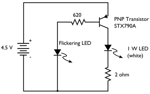
Windell Oskay, over at Evil Mad Scientist, put together a great post "Does this LED sound funny to you?" in which he uses a PNP transistor to amplify the signal being drawn by the flicker LED. he then sends this to a LED and then a speaker. Unfortunately the STX790a transistor he selects has been discontinued, and I had some difficulty finding a similar spec’d transistor (ie stopped after 10 minutes of google-ing). I did have some PN2907 PNP transistors lying around. I tried one of those in Oskay’s circuit.
The flicker LED would flicker nicely, but unfortunately just caused the transistor to continuously conduct. The secondary LED would just stay lit, perhaps a bit dimmer than usual. Interestingly enough, when I hooked the transistor up backwards (still in the same place in the circuit, but just swapping the collector and the emitter leads) both the flicker LED and the secondary LED would flicker. The effect seemed stable. The transistor was still working as a PNP transistor, but just with unknown specs. Seemed kind of sketchy and not exactly something I could recommend to others… So back to my parts box…
I have several "logic-level" N-channel mosfets lying around in my parts box, specifically the IRLB8721 and the FQP30N06L. I use both of these frequently for rapid switching (PWM and otherwise) up to a few amps of current at 12V.
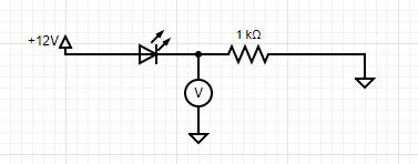
I set up my mini digital oscilloscope to query the voltage at a few points along a simple flicker LED circuit and found that I could reliably detect the signal between the LED and the resistor when they were arranged like this.
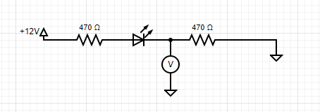
This meant that I could replace the oscilloscope with my mosfet and use that to turn on and off my secondary LED. In order to protect the LED from the few picoseconds of in rush current to the gate when the fet was switching, I split the resistor before and after the LED like this-
This gave me the following signal
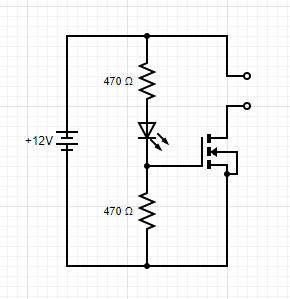
Voltage reliably switches back and forth between 0 and 5v. Perfect for running my mosfet. (Interestingly, it looks like the flicker LED uses an approximately 400Hz PWM signal and varies the duty cycle to change brightness. Most of the time the LED is full on, but will give “flickers” of various lower duty cycles.) This gave me the final circuit diagram.
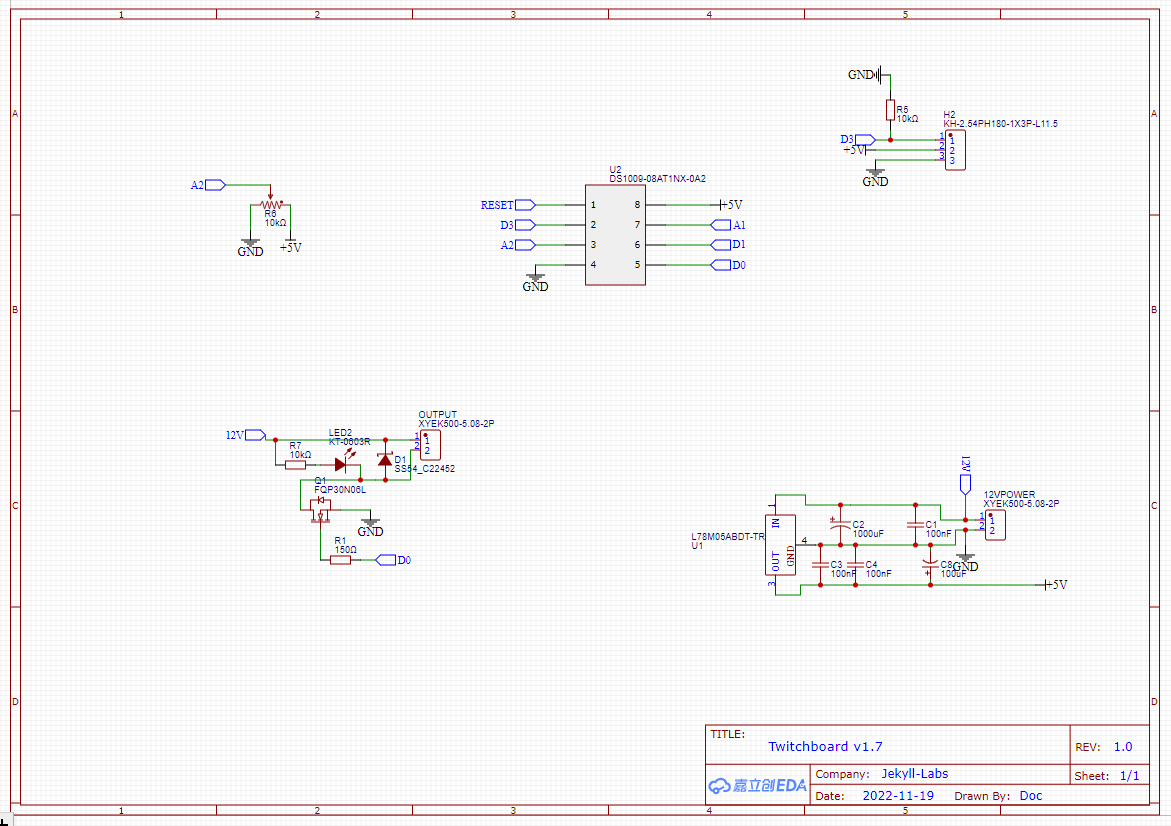
The circuit is easy to put together on a breadboard, but I wanted a cleaner solution that could run flicker lights for several pumpkins, so I put together a PCB.
Here’s a picture of the board assembled and mounted. It has holes placed such that a zip tie can fasten the board to a 1/2” PVC T fitting. I can then slide a plastic cup over the top. This lets me mount it in the yard, covered from rain, and able to drain well.
And finally, here’s a video of the circuit in action and my assembly of an electronic PVC candle.
So, I’m still rather partial to the firelight effect on my Lightboard, but if you’re looking for something that doesn’t need any coding, this circuit is a great option. You can easily put this together on a breadboard, but if you’d like a more streamlined solution, I’m happy to put a PCB board in the mail. Check out the Jekyll-Labs Store and contact me through the link in the side bar.
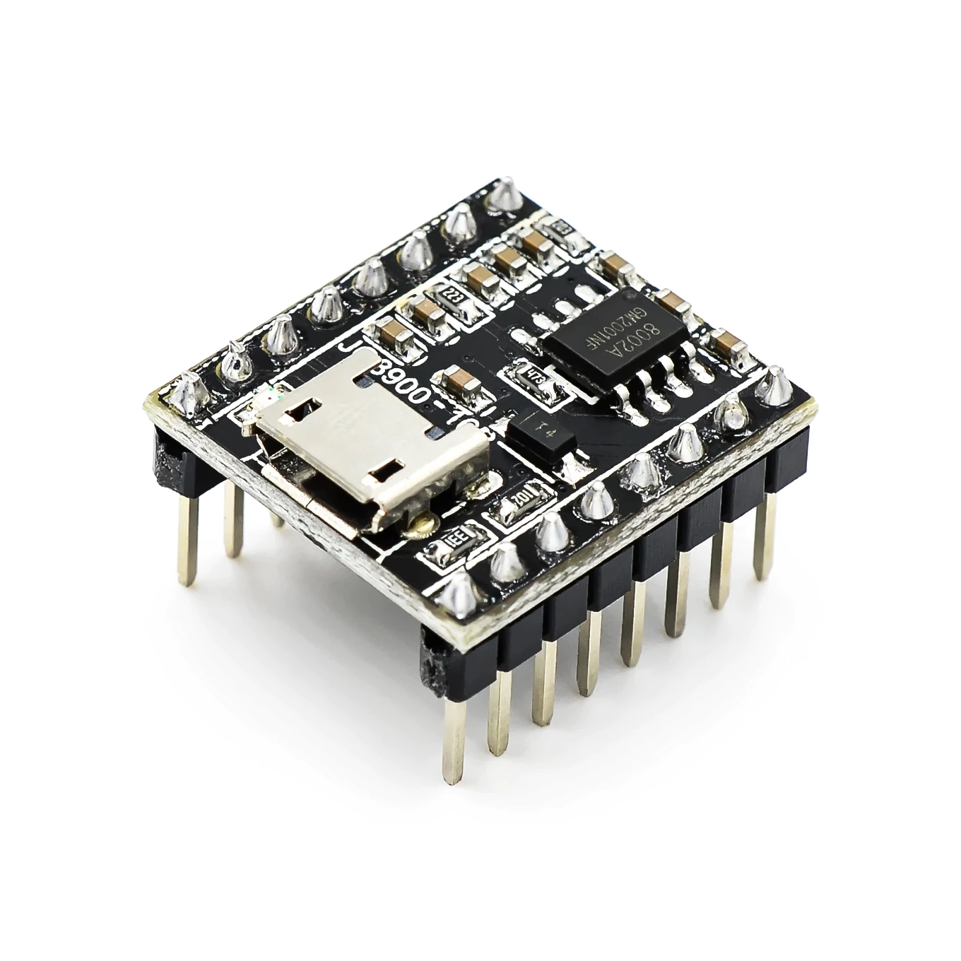
So, I'm really pleased with this new (to me) MP3 player that seems like a nice alternative to the DFPlayer. Its manual is sometimes hard to find so I've hosted a copy of the PFD below. First and foremost, it has onboard storage for audio files. Your computer recognizes it as a USB drive, so it's a simple plug-n-play then drag-n-drop.
To trigger the audio the JQ8900 has a few options:
(1) There is a two-way serial connection using the Rx and Tx pins. This is the most robust way with many options analogous to the DFPlayer serial connection. Unfortunately, the serial commands are different from the DFPlayer, and I'm not aware of an existing Arduino library. Fortunately, the JQ8900 seems to be based on the JQ8400. The JQ8400 does have an Arduino library, but I have not personally used it. Both the JQ8900 and the JQ8400 have manuals that have been translated into English and have good information.
With the JQ8900, I'm partial to using the serial commands directly. "AA 06 00 B0" will play the next file. I've included below some example code that will every 5 seconds play the next file in sequence.
(2) There is a single wire input mode available using the VPP pin. I haven't personally used this, but there are many examples online (unfortunately for me, mostly in Chinese)
(3) The JQ8900 has 7 trigger pins. These are great. When the IO1 pin is connected to ground the JQ8900 will play the file named 00001.mp3 (and so on). This works well for manual buttons as well as microcontrollers. With this board, I used an ATTINY85 sending a signal to an NPN transistor to connect IO1 to ground.
Audio output is either speaker output (appears to be a 3W amplifier) or line level output via DAC and ground. For both outputs, the JQ8900 collapses the right and left channels into a single mono channel. This is a disadvantage as compared to the DFPlayer, which has mono output for the speaker, but stereo ouput for line level. If you need stereo output, the JQ8900 may not be the board for you.